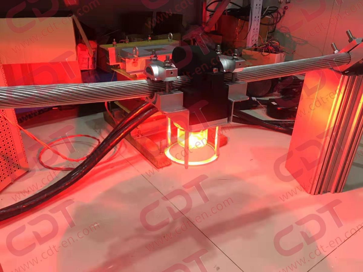
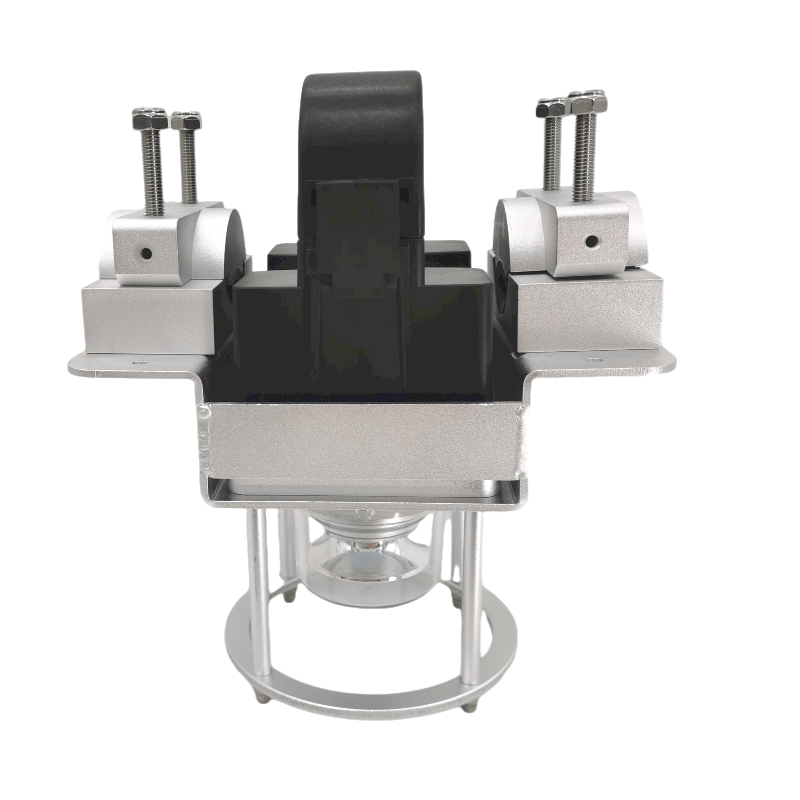
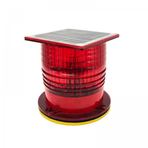
CK-11 Conductor Marking Light
Conductor marking lights enhance the nighttime visibility of transmission line catenary wires, especially near airports, heliports, and river crossings. These conductor marking light effectively mark and illuminate overhead power line support structures (towers) and high-voltage transmission line catenary wires.
Working Principle
Farady's Law of induction involving Magnetic Flux flowing
through a circuit which powers the warning light.
Inductive Magnetic Device
The Warning light is powered by the magnetic field surrounding the power distribution wire and uses an electronic circuit integrated in a compact clamp-on warning light. The operating principle is that of a Rogowski coil, similar to a current transformer.
This solution is usually intended for medium and high voltage lines up to 500 kV. However inductive coupling devices are able to work on any AC at 50 Hz or 60 Hz, from 15A up to 2000A.
Production Description
Compliance
| - ICAO Annex 14, Volume I, Eighth Edition, dated July 2019 |
● The product adopts LED light source, uses wire to induce power supply, and the interconnection is long.
● The product is light in weight, compact in design, and easy to install.
● Main purpose and scope of application: This product is mainly used as a warning on AC high voltage lines below 500KV.
● The light intensity, light color, and light emitting angle conform to the ICAO aviation obstruction light standard.
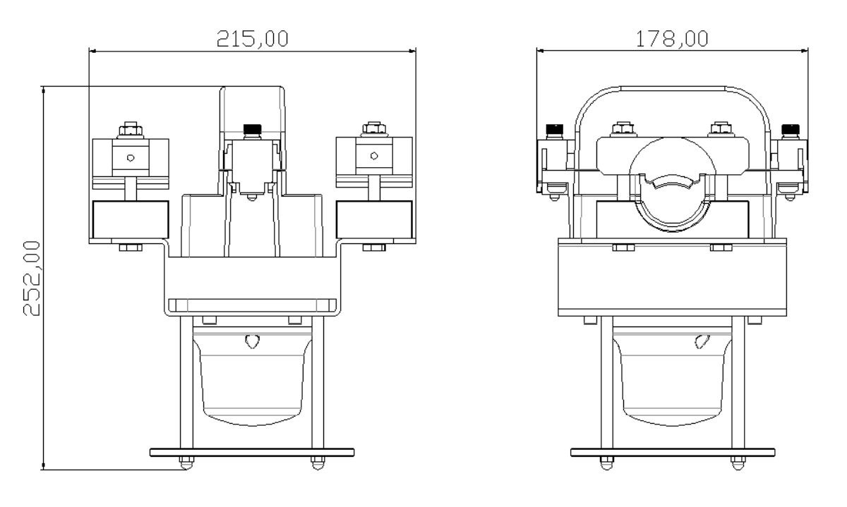
| Item Name | Parameter |
| LED Source | LED |
| Emitting Color | Red |
| Horizontal beam angle | 360° |
| Vertical beam angle | 10° |
| Light Intensity | 15A<Conductor Current<50A,>10cd
Conductor Current>50A, >32cd |
| Adapt to wire voltage | AC 1-500KV |
| Adapt to wire current | 15A-2000A |
| LifeSpan | >100,000 hours |
| Suitable high-voltage Conductor Diameter | 15-40mm |
| Operating temperature | -40℃-+65℃ |
| Relative humidity | 0%~95% |
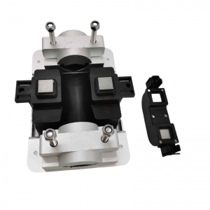
When the high-voltage line is out of power, separate the fastening parts 1, 2, and 3 of the product from the assembly of the product.
Bring the product close to the high-voltage line, and make the high-voltage line pass through the product's trunking.
Put the accessory 2 of the product into the main body of the product. The accessory should be fully assembled in place, and the screw 5 should be tightened.
Put the accessory 1 of the product into the original assembly position, and tighten the nuts 3 and 4. The product is fastened to the high-voltage line.
